Special-purpose machinery: from design to delivery, with conformity built in
Special-purpose machinery addresses requirements that standard equipment cannot adequately meet: preparing materials, assembling, dosing, handling or testing a process. Its success depends on continuity between design, manufacturing, controls and testing. Safety is developed throughout those stages.
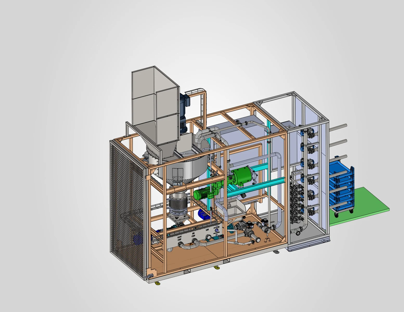
1. Define what the machine must do
The specification establishes materials, capacity, throughput, expected quality and operating conditions. It also covers utilities, space, neighbouring equipment, cleaning and maintenance.
Acceptance criteria should be measurable: which materials, at what load, for how long and within which tolerances? These decisions guide engineering and align expectations before delivery.
2. Design mechanics, fluids and controls together
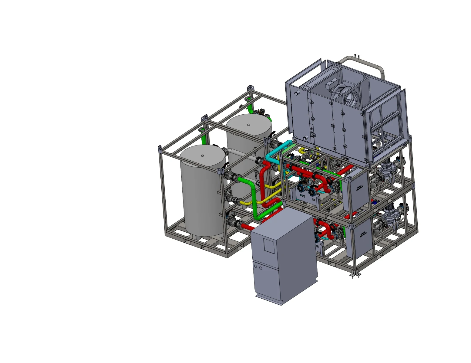
Models and drawings address layout, access and assembly. Fluid and electrical diagrams, input/output lists and functional specifications describe operation. All disciplines need consistent assumptions.
For example, selecting a pump on a preparation skid involves flow and material properties as well as maintenance, operating permissions, feedback and fault responses. The component and its integration must be considered together.
3. Reduce risks during design
Assessment covers intended use and reasonably foreseeable misuse across relevant lifecycle stages. First eliminate or reduce hazards through design, then provide necessary safeguards and information on residual risks. Instructions do not substitute for feasible protective measures.
For DIS, project preparation therefore considers operator access, maintenance, energy sources and failure scenarios before manufacturing decisions are frozen. Identified safety functions require appropriate design and validation.
4. Identify the manufacturer and supply boundary
Complete machinery and partly completed machinery follow different requirements. Partly completed machinery is intended for incorporation and cannot perform a specific application on its own. Classification depends on the actual equipment, not on a preferred allocation of obligations.
Under the Directive, complete machinery follows the applicable conformity procedure, with an EC declaration of conformity, instructions and CE marking. Partly completed machinery requires relevant technical documentation, a declaration of incorporation and assembly instructions; it does not carry CE marking under the Machinery Directive.
For an assembly, identify the final manufacturer and integration interfaces. The client can hold that role where the actual arrangement and obligations support it. Commissioning an audit or physically attaching a plate does not by itself establish the role.
INRS — Definitions · Directive 2006/42/EC: Articles 5 and 13, Annexes II, VI and VII
5. Build and inspect the equipment
Manufacturing brings together mechanical parts, pipework, panels and software. Track drawings, component identification and changes made during assembly. Review changes affecting operation or safety before approval.
An inspection body or specialist can assess a defined scope. Its report contributes to the technical evidence without replacing the manufacturer’s overall process. Whether a notified body is required depends on the machinery category and applicable procedure, not simply on the equipment being custom-built.
6. Test before acceptance
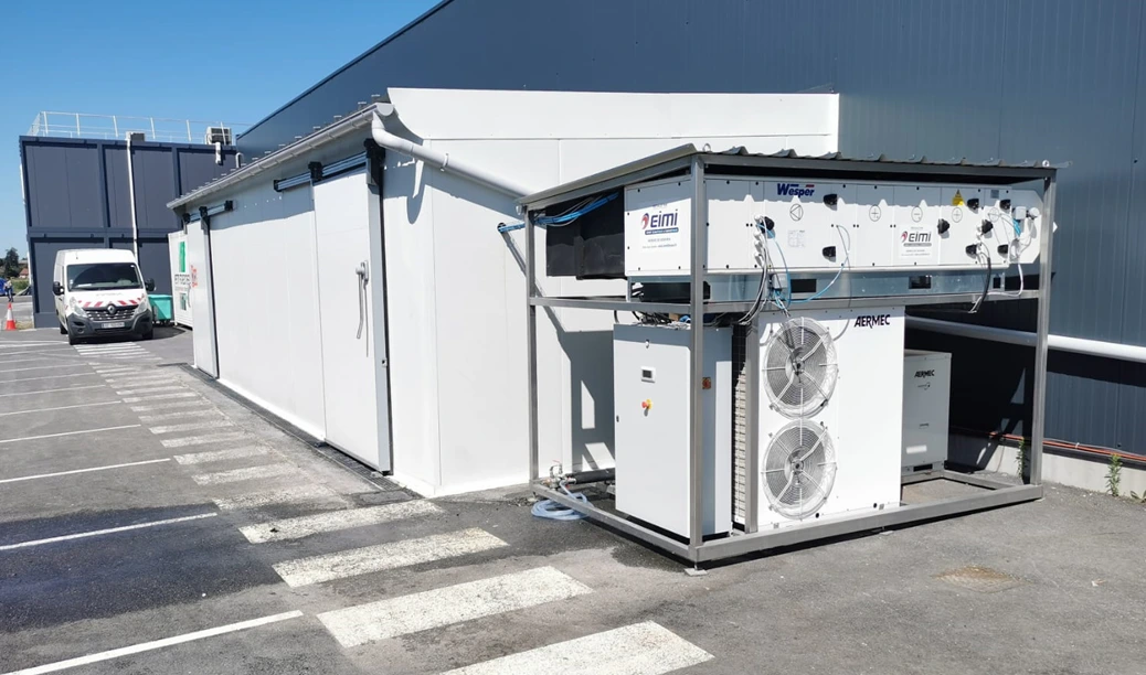
Factory and site acceptance tests, often called FAT and SAT, are organised to suit the project. They check agreed operating conditions and integration.
- Verify inputs/outputs, sequences and operating modes.
- Test and document safety functions using the selected protocol.
- Measure performance against explicit conditions and criteria.
- Record deviations, corrections and outstanding items.
- Identify delivered drawings, settings and software versions.
An acceptance record documents what was tested and accepted. It does not alone establish exhaustive conformity or remove all post-delivery responsibility.
7. Prepare operation and future changes
Handover includes required instructions and documents, plus agreed operating deliverables such as updated drawings, maintenance guidance and identified spare parts. The relevant responsible party compiles and retains the regulatory technical file; handing the entire file to the client is not a general obligation.
Subsequent modifications should remain traceable. Recording the delivered state distinguishes the validated configuration from changes requiring further assessment.
The DIS approach: stay connected to execution
DIS combines design, specialist coordination and on-site integration. Mechanical, electrical, controls and installation work share a defined scope, with deliverables and tests agreed from the outset.
The aim is useful, operable and documented equipment, with applicable requirements integrated into its design. Conformity is assessed for each machine and intended use; it cannot be reduced to a blanket commercial promise of “CE certification”.